Inputs
This is not really an advanced topic but a repeat (more or less) of part 9 of the tutorial it may have some information for advanced users on how to set up registers for input and ADC. It is in fact a copy of the original tutorial.
Input has been left until now so that we can use the display as a neat device rather than using the terminal screen.
Digital Inputs
All of the ports can be configured to be either input or output and this is done with the TRIS register.
Input: Project 1
http://byvac.com/mBlib/flb/Tutorial/PIC32MX1_Family/30_Input/Project_1.bas
// Digital input
//
// Port A registers
constant ANSELA          0xBF886000
constant ANSELACLR       0xBF886004
constant ANSELASET       0xBF886008
constant ANSELAINV       0xBF88600C
constant TRISA           0xBF886010
constant TRISACLR        0xBF886014
constant TRISASET        0xBF886018
constant TRISAINV        0xBF88601C
constant PORTA           0xBF886020
constant LATA            0xBF886030
constant PORTACLR        0xBF886024
constant PORTASET        0xBF886028
constant PORTAINV        0xBF88602C
constant CNPUASET        0xBF886058

constant INP 1 << 0

// *****************************************************************************
// Initialise RA0 as in input, this is pin 1
// *****************************************************************************
function x()
dim count=0
	num_disp4(count)
	@TRISASET = INP // set as i/p
	@CNPUASET = INP // enable pull up
	@ANSELACLR =INP // set for digital I/O
	while  comkey?(2) = 0
		if (peek(PORTA) & INP) = 0 then
			count = count + 1
			num_disp4(count)
		endif
		if count > 9999 then;count=0;endif
	wend
endf
Connect a short length of wire to pin 2, this is RA0 and we are going to use this as an input. Load project_1 and have a look at function x() (end of the code)
INP is set to 1 at the top of the file. TRISASET sets the pin to be an input, CNPUASET sets a weak pull up resistor to keep the pin in a high state, there is also a weak pull down, finally ANSELACLR sets the pin to be a digital input rather than an analogue input.
Type seg_start and then x. The display should read 0. Now connect the other end of the short wire to ground (pin 8 is the nearest) and the counter will increment – a push button would do. No matter how quick you connect and disconnect the counter always counts several hundreds.
Suppose we wanted it to count just 1 each time it was connected to ground. One method is in project_2
Input: Project 2
http://byvac.com/mBlib/flb/Tutorial/PIC32MX1_Family/30_Input/Project_2.bas
// Digital input
//
// Port A registers
constant ANSELA          0xBF886000
constant ANSELACLR       0xBF886004
constant ANSELASET       0xBF886008
constant ANSELAINV       0xBF88600C
constant TRISA           0xBF886010
constant TRISACLR        0xBF886014
constant TRISASET        0xBF886018
constant TRISAINV        0xBF88601C
constant PORTA           0xBF886020
constant LATA            0xBF886030
constant PORTACLR        0xBF886024
constant PORTASET        0xBF886028
constant PORTAINV        0xBF88602C
constant CNPUASET        0xBF886058

constant INP 1 << 0

// *****************************************************************************
// Initialise RA0 as in input, this is pin 1
// *****************************************************************************
function x()
dim count=0
	num_disp4(count)
	@TRISASET = INP // set as i/p
	@CNPUASET = INP // enable pull up
	@ANSELACLR =INP // set for digital I/O
	while  comkey?(2) = 0
		if (peek(PORTA) & INP) = 0 then
			count = count + 1
			num_disp4(count)
			while (peek(PORTA) & INP) = 0
			wend
		endif
		if count > 9999 then;count=0;endif
	wend
endf
Load this project, type seg_start then x and see if it works.
The additional lines are the while and wend. What does happen is that when contact is made with ground the result is 0 and so the first ‘if’ lets the counter increment. The while statement does not let it go past until it is removed from the ground so why does it not work very well and sometimes count more than one?
This is called switch bounce, the fact is that no matter how good a switch is, and that includes the bit of wire when it is pressed on to the ground (pin 8 say) it bounces on the connector – touching – not touching etc. and because the processor reacts so fast, this is counted.
This is a practical matter as switches are an essential part of a control system and must be dealt with. The easiest, and probably best method is to simply introduce a delay.
Input: Project 2a
http://byvac.com/mBlib/flb/Tutorial/PIC32MX1_Family/30_Input/Project_2a.bas
// Digital input
//
// Port A registers
constant ANSELA          0xBF886000
constant ANSELACLR       0xBF886004
constant ANSELASET       0xBF886008
constant ANSELAINV       0xBF88600C
constant TRISA           0xBF886010
constant TRISACLR        0xBF886014
constant TRISASET        0xBF886018
constant TRISAINV        0xBF88601C
constant PORTA           0xBF886020
constant LATA            0xBF886030
constant PORTACLR        0xBF886024
constant PORTASET        0xBF886028
constant PORTAINV        0xBF88602C
constant CNPUASET        0xBF886058

constant INP 1 << 0

// *****************************************************************************
// Initialise RA0 as in input, this is pin 1
// *****************************************************************************
function x()
dim count=0
	num_disp4(count)
	@TRISASET = INP // set as i/p
	@CNPUASET = INP // enable pull up
	@ANSELACLR =INP // set for digital I/O
	while  comkey?(2) = 0
		if (peek(PORTA) & INP) = 0 then
			count = count + 1
			num_disp4(count)
			wait(100)
			while (peek(PORTA) & INP) = 0
			wend
			wait(100)
		endif
		if count > 9999 then;count=0;endif
	wend
endf
Load this project, type seg_start and then x. Not perfect but much improved. This just introduces one delay. Switch bounce lasts about 50mS or less, the bit of wire will need a longer time. As you can see delay is also required when going from 0 to 1.
To be the most accurate the function needs extending so that after the delay the port should be checked again, If it is still low then this is a valid on. Like wise when going from 0 (on) to 1 (off), after the delay the port can be checked to see if it is really 1.
Analogue
This processor is equipped with an analogue to digital converter so that an analogue signal such as a voltage can be read, digitised and then presented to a register as a number. For maximum flexibility there are numerous options that are all controlled by clearing or setting bits inside registers. All of which can be done of course using mB.
For this processor the following is available:
RA0 AN0
RA1 AN1
RB0 AN2
RB1 AN3
RB2 AN4
RB3 AN5
RB12 AN10
RB13 AN11
RB14 AN10
RB15 AN9
We will be using AN0 connected to RA0 (pin 2). First wire the trimmer as shown in the diagram. See the kit list item H
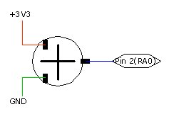
This is looking down on top of the trimmer, it should push easily into the breadboard. Make sure that you get the ground and +3V3 to the left and right of the trimmer (pins 1 and 2 on the trimmer). There will be smoke if you get one of these on the centre pin (pin 3). When the trimmer is turned there will be a voltage on the centre pin that will represent how much the trimmer has been turned. Fully to the ground side and there will be 0 volts, fully to the 3.3V side and there will be 3.3V. Anything in-between will be a portion of that. It is this voltage that we are going to measure on pin 2 (AN0)(pin 3 to the trimmer).
Input: Project 3
http://byvac.com/mBlib/flb/Tutorial/PIC32MX1_Family/30_Input/Project_3.bas
// Analogue input
//
// Registers
constant ANSELASET       0xBF886008
constant TRISASET        0xBF886018
constant AD1CON1         0xBF809000
constant AD1CON1SET      0xBF809008
constant AD1CON2         0xBF809010
constant AD1CON3         0xBF809020
constant AD1CSSL         0xBF809050
constant AD1CHS          0xBF809040
constant ADC1BUF0        0xBF809070
// adc
constant SAMPLE 5
constant CONVERSION 5
constant INP 1 << 0		// RA0

// *****************************************************************************
// Set up ADC for auto ample and scan
// *****************************************************************************
function adc_init()
	@TRISASET = INP // set as i/p
	@ANSELASET = INP // set as analogue
	@AD1CON3 = 0 // reset first, clock derived from PBCLK
	@AD1CON3 = (SAMPLE << 8) | CONVERSION
	@AD1CON2 = 0
	@AD1CON1 = 0x80e0 // auto conversion + turn on ADC
	@AD1CSSL = 0
endf
// *****************************************************************************
// sample selected channel and return value
// *****************************************************************************
function adc_get(channel)
	@AD1CHS = channel << 16
	@AD1CON1SET = 2 // start conversion
	while (peek(AD1CON1) & 1) = 0; wend
	return @ADC1BUF0
endf

function x()
	print adc_get(0)
endf
Load this project, type adc_init and then x. Each time you press x a conversion is done and the result shown on the screen. Rotate the trimmer and press x again for different results.
Some points to note:
The maximum reading should be 1023, you may get slightly less than this depending on the trimmer, it may not connect very well to the positive end, also there may be some loss in the wires. The reading is relative to the analogue reference (Vrefh and Vrefl). The is set in AD1CON2 and project_3 set this to be the power supply pins. For accurate conversions a voltage reference can be used. Set the trimmer to midway and press x a few times. Quite often you will not see the same reading twice. The ADC is accurate and it is reflecting what is on the pin. The point, is that the pin is infact a fluctuating voltage – only slightly but depending on what the sample is taken it may be on a high or low point. To counter this we normally take the average of several readings or place a capacitor on the input pin. This becomes more obvious in Project_3a.
Unfortunately it is beyond the scope of this tutorial to go into how the ADC works and all of the options that are available. If you simply want an analogue input then the code in Project_3 is good enough.
Input: Project 3a
http://byvac.com/mBlib/flb/Tutorial/PIC32MX1_Family/30_Input/Project_3a.bas
// Analogue input
//
// Registers
constant ANSELASET       0xBF886008
constant TRISASET        0xBF886018
constant AD1CON1         0xBF809000
constant AD1CON1SET      0xBF809008
constant AD1CON2         0xBF809010
constant AD1CON3         0xBF809020
constant AD1CSSL         0xBF809050
constant AD1CHS          0xBF809040
constant ADC1BUF0        0xBF809070
// adc
constant SAMPLE 5
constant CONVERSION 5
constant INP 1 << 0		// RA0

// *****************************************************************************
// Set up ADC for auto ample and scan
// *****************************************************************************
function adc_init()
	@TRISASET = INP // set as i/p
	@ANSELASET = INP // set as analogue
	@AD1CON3 = 0 // reset first, clock derived from PBCLK
	@AD1CON3 = (SAMPLE << 8) | CONVERSION
	@AD1CON2 = 0
	@AD1CON1 = 0x80e0 // auto conversion + turn on ADC
	@AD1CSSL = 0
endf
// *****************************************************************************
// sample selected channel and return value
// *****************************************************************************
function adc_get(channel)
	@AD1CHS = channel << 16
	@AD1CON1SET = 2 // start conversion
	while (peek(AD1CON1) & 1) = 0; wend
	return @ADC1BUF0
endf

function go()
dim j, avg
	adc_init()
	seg_start()  // get the LED display going
	while comkey?(2) = 0
		avg=0
		for j = 1 to 30
			avg = avg + adc_get(0)
		next
		num_disp4(avg/30)
	wend
endf
This project presents a great starting point for experimentation. It does show very clearly the practical problems of Analogue to digital conversion. Load and type go().
NOTE:
the ‘go’ routine contains the start up code for the LED (seg_start()), this should only be run once per reset as it adds the interrupt to the interrupt table. If you intend experimenting then move this out of the go function.
The value is now presented on to the LED display. Here are some problems to solve:
- Why may there be a problem with this “num_disp4(avg/30)” line? (hint divide by 0)
- Even with averaging the end digit on the display tends to fluctuate between readings. Increasing the number of averages is not the solution.
The answer to 2 is always dependant on the final application but it is more difficult to get an even display than might at first be imagined.